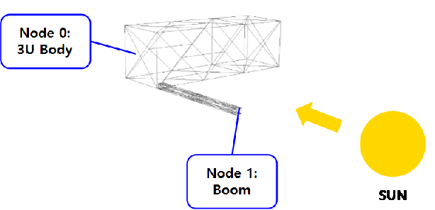
Why does the body potential change more significantly when only the boom material is changed in a 3U + boom structure?

Hello,

I am using SPIS to investigate surface charging on a 3U CubeSat equipped with a boom. The boom is assumed to have dimensions of 0.01 × 0.01 × 0.2 m and to be attached to one end of the 3U satellite. To examine how the material properties of the spacecraft affect the surface charging of both the main body and the boom, I performed the following two simulations.

(1) Case 1: both the spacecraft body and the boom were set as Al2K
(2) Case 2: the spacecraft body was set as Al2K, while the boom was set as Kapton

However, even though the boom material was changed, the boom potential remained almost the same, while the body potential changed significantly. Since this was intended to represent night conditions, photoemission was assumed to be absent. The emission settings were as follows: Electron Secondary Emission = 3, Proton Secondary Emission = 0, PhotoEmission = 0.

(1) Case 1: body (Al2K) potential = -11953 V, boom (Al2K) potential = -11526 V
(2) Case 2: body (Al2K) potential = -14921 V, boom (Kapton) potential = -11392 V

According to the material properties provided in SPIS, the relevant characteristics of Al2K and Kapton are as follows.

  • Al2K secondary electron emission peak energy and yield: 0.3, 0.97

  • Kapton secondary electron emission peak energy and yield: 0.2, 1.9

There are three aspects that I do not understand.

(1) Why did the body potential change significantly even though only the boom material was changed?
(2) Why did the boom potential remain almost the same in Cases 1 and 2, even though the secondary electron yield of Kapton is larger than that of Al2K?
(3) In Case 2, the Kapton boom charged slightly more positively than the Al2K boom in Case 1, but why is the increase in negative charging of the body in Case 2 much larger than the difference in boom potential?

If anyone has encountered a similar case or has any idea about the cause of even one of these points, I would greatly appreciate it if you could share your thoughts. It is also possible that these results were caused by an error in our simulation setup, so I would be very grateful for any advice on possible mistakes in the simulation.

Simulation plasma conditions:

  • Ambient plasma: (O+ ions) Ti = 0.2 eV, Ti = 108 m-3 / (electrons) Te = 0.2 eV, Ne = 108 m-3

  • Auroral electrons: (Thermal electrons) Tth = 11 keV, Nth = 107 m-3

  • Spacecraft velocity: 7500 m/s

  • Simulation time: 5 s

Hi Seohyun, I take it the body and the boom are electronically or physically connected? So some current can flow from one surface to the other? That could allow the change of material to change the flow of currents to/from the S/C and thus the equilibrium potential of each in either direction.

Also, is this non-conductive Kapton? What is your definition of its potential then, as it probably should have a non-uniform potential distribution on the surface. I suspect what you are describing is the node ground potential, but the surfaces of the boom near the spacecraft can be at any potential and current can flow from them.

That said, I am not sure your simulation is not buggy, LEO polar is a challenging environment. If you have a significant potential at your boundary, or ions are ridiculously depleted, then this is a tell-tale sign of an unstable simulation.

Hi, thank you very much for your reply.

In my current setup, I did not assign any explicit electrical connection between the nodes. So, in the circuit sense, the body-side nodes and boom-side nodes were left electrically isolated from each other. The minimum spacing in the relevant region is about 3 mm. Also, the Kapton I used is non-conductive Kapton.

From your comment, I would like to make sure I understood your point correctly.

Are you suggesting that, even without an explicit node-to-node electrical connection, changing the boom material could still modify the overall current balance of the spacecraft through electrostatic or capacitive coupling, and therefore shift the equilibrium potential of the body nodes as well?

Also, when you mention that the Kapton surface should probably have a non-uniform potential distribution, do you mean that the quantity I am comparing in SPIS may only be the node ground potential, rather than a physically uniform surface potential over the whole Kapton region? If so, would that be a possible reason why the body-node potential appears to change more strongly than I expected when only the boom material was changed?

Finally, thank you also for pointing out the possibility of an unstable simulation. I would appreciate it if you could clarify which output or diagnostic would be the most useful to check this. For example, should I primarily look at the boundary potential, ion depletion, collected currents, or some other indicator?

Thank you again for your help.

Hi Seohyun. Are you saying that the boom and body are separated by 3 mms? I would expect that to be a undue driver of the simulation complexity as SPIS needs to resolve that gap volume well to allow plasma to flow through it in a realistic fashion, it’s easy to make the simulation unstable because of that, and the knowledge gain is minimal. I think physically connecting them would be more realistic.

On your questions, paragraph 1. the answer is yes if these materials are physically connected. If the capacitive coupling goes through the plasma, and I don’t expect this effect to be as large as you describe.

paragrah 2. Yes, I am. Have a look at surface potentials. plot the volume potential and look at the potential distribution on the surface. the “min/max/average surface and ground potentials” are just three/four points, but the reality is a full distribution. Indeed.

paragraph 3. I pointed out some already. collected currents vs time are only one diagnostic, the truth is in the plasma. If you see plasma potential or plasma density features you cannot explain, you probably hit some instability. The good thing about numerical instabilities is that it cares about ridiculous things that the universe does not. If you increase the simulation volume or enhance mesh resolution and you see a large effect, you also know that your simulation hit some instability.

Best of luck