SPIS - EP, How to calculate electric currents by HET in circuit

Hello everyone!
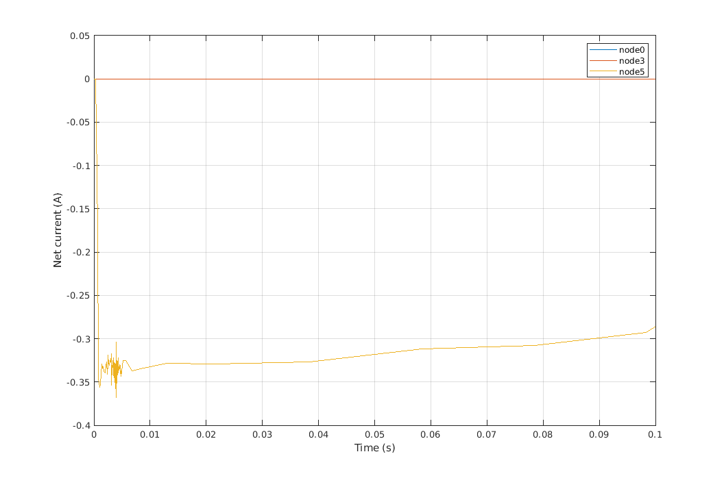
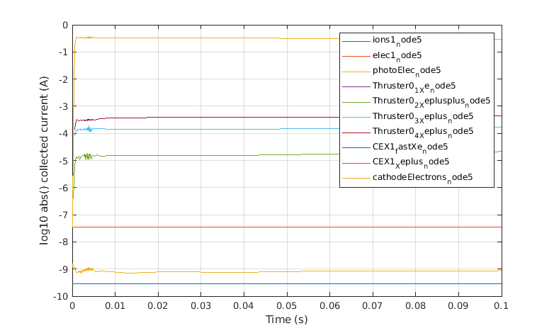
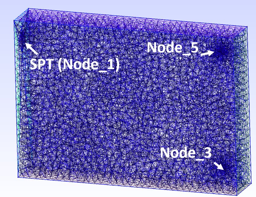
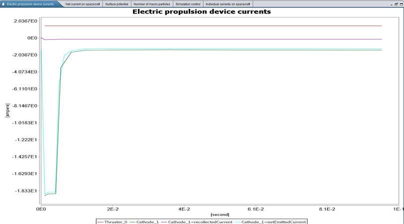
I work in a laboratory with Hall thrusters, and it just so happens that I need to understand what current of ions and electrons (especially electrons) flows to the surface of a spacecraft under a potential comparable to the accelerating potential of the thruster. We have already conducted an experiment in the laboratory and obtained linear volt-ampere characteristics of probes in plasma, i.e. the dependence of current on voltage on a flat probe located in the thruster plasma. And we obtained linear characteristics, where, logically, the electron current goes to the positive potential, and the ion current to the negative. But when modeling the same situation in SPIS, I encountered the fact that the net electric current to the nodes corresponding to the flat probes does not coincide at all with the experimental results. Moreover, it is not clear whether the electric current in the circuit is closed correctly. The electric circuit is as simple as possible: between nodes 3 and 5 (these are electrodes - probes) there is a potential difference, for example 50, 100, 200, and 300 Volts. How can I understand what current flows between nodes 3 and 5? If you look at the currents on the surface, it turns out very strange: When the potential of the electric field (positive) on the probe decreases, the ion current for some reason decreases, although it should, on the contrary, better get to the surface and increase accordingly. If anyone has encountered such a situation, then please explain how electric circuits work, how to see what current flows in them?

I am attaching the calculation files of the model at this link: SPIS-EP Current  – Google Drive
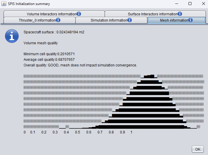
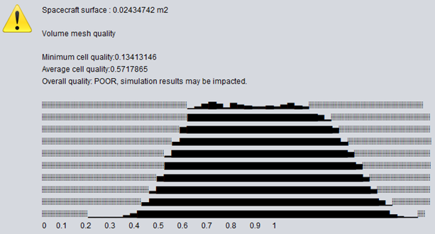
And some pictures:

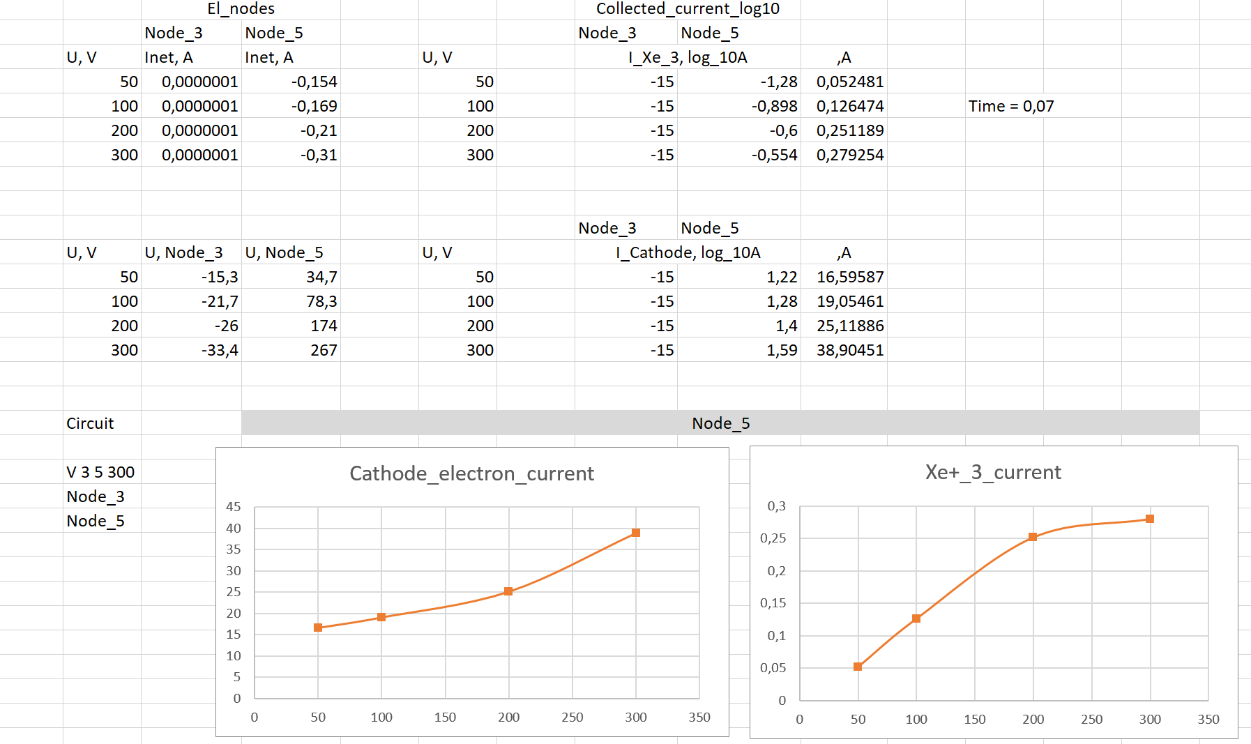
Exel file inside g-link.

Thanks in advance for your reply, advice or any help!

I ask you to help a colleague (Please). We both encountered the same thing.
We would appreciate any clarification.

Hi Ivan, Karolina.
A few words of warning,

  1. Don’t use unlimited ‘UnlimitedGlobalMaxwellBoltzmannVolDistrib’ for anything. I guess I could have said "if you don’t know what you’re doing’, but it’s such an unrealistic approximation of densities and currents at attractive potential that I think it should be fully deprecated. KineticMaxwellBoltzmannVolDistrib is there if you really need speed and performance without unreasonable approximations, but why not default to PICVolDistrib.

Also, GlobalMaxwellBoltzmannVolDistrib distribution of ions is not recommended for ions in the manual. Your temperatures are pretty high in both of these cases, in comparison to the potentials, so it hasn’t affected your results too much so far, but it’s asking for trouble. Just use PIC.

I also think the input plasma densities are strange, it’s not a quasineutral plasma at start, but maybe that is as intended.

  1. As I’m sure you’ve noticed, SPIS is telling you that your mesh is of bad quality. Optimize the .msh in GMSH using both or any optimization method until you get your quality under control. you may need to increase resolution where necessary.

  2. You are extracting results before the simulation has converged. As you probably noticed, the 300V simulation potentials are still evolving for node 3 and 5, and a comparison to lab measurements will be useless

And onto your actual question. I couldn’t reproduce your google sheet currents (using the emitted and collected currents, the maximum I could see was -0.3 Amps in node 5 in the 300V case, from the cathodeelectrons. I think there is some issue with how you or SPIS have extracted these log10 currents. I always look at the collectedcurrents.txt, emittedcurrents.txt and potentials.txt in the output folder of the numkernel, and they make sense to me.

log10(abs(collectedcurrents for node ==5)